Gears

Introduction
A gear is a rotating circular machine part having cut teeth which mesh with another toothed part to transmit torque. A gear may also be known informally as a cog. Geared devices can change the speed, torque, and direction of a power source. Gears of different sizes produce a change in torque, creating a mechanical advantage, through their gear ratio.
Types of Gears
Spur gear
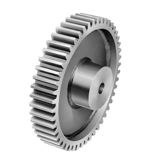
Spur gears or straight-cut gears are the simplest type of gear. They consist of a cylinder or disk with teeth projecting radially.

Helical gears
Helical or “dry fixed” gears offer a refinement over spur gears. The leading edges of the teeth are not parallel to the axis of rotation, but are set at an angle. Since the gear is curved, this angling makes the tooth shape a segment of a helix.

Crown gear
Crown gears or contrate gears are a particular form of bevel gear whose teeth project at right angles to the plane of the wheel, in their orientation the teeth resemble the points on a crown
Double helical gear
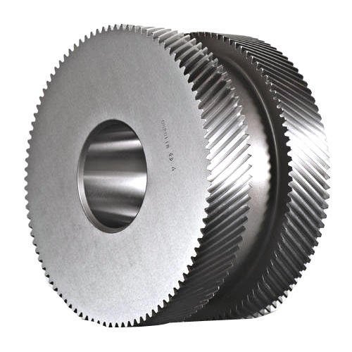
Double helical gears are a variation of helical gears in which two helical faces are placed next to each other with a gap separating them. Each face has identical, but opposite, helix angles. Employing a double helical set of gears eliminates thrust loads and offers the possibility of even greater tooth overlap and smoother operation. Like the helical gear, double helical en gears are commonly used enclosed gear drives.
Herringbone gear
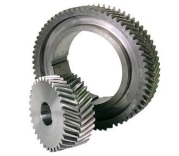
Herringbone gears are very similar to the double helical gear, but they do not have a gap separating the two helical faces. Herringbone gears are typically smaller than the comparable double helical, and are ideally suited for high shock and vibration applications. Herringbone gearing is not used very often due to their manufacturing difficulties and high cost.
Bevel gear
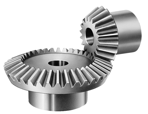
Bevel gears are most commonly used to transmit power between shafts that intersect at a 90 degree angle. They are used in applications where a right angle gear drive is required. Bevel gears are generally more costly and are not able to transmit as much torque, per size, as a parallel shaft arrangement.
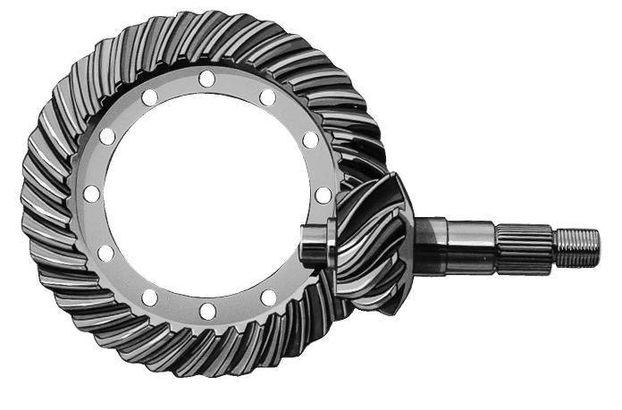
Hypoid gear
Hypoid gears look very much like a spiral bevel gear but they operate on shafts which do not intersect, which is the case with a spiral bevel gear. In the hypoid arrangement because the pinion is set on a different plane than the gear, the shafts are supported by the bearings on either end of the shaft.

Spiral bevel gear
Spiral bevel gears are bevel gears with curved tooth lines. Due to higher tooth contact ratio, they are superior to straight bevel gears in efficiency, strength, vibration and noise. On the other hand, they are more difficult to produce. Also, because the teeth are curved, they cause thrust forces in the axial direction. Within the spiral bevel gears, the one with the zero twisting angle is called zero bevel gear.
Screw gear
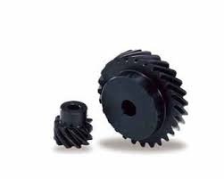
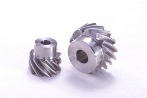
Screw gears are a pair of same hand helical gears with the twist angle of 45° on non-parallel, non-intersecting shafts. Because the tooth contact is a point, their load carrying capacity is low and they are not suitable for large power transmission. Since power is transmitted by the sliding of the tooth surfaces, it is necessary to pay attention to lubrication when using screw gears. There are no restrictions as far as the combinations of number of teeth.
Miter gear
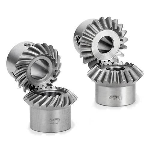
Miter gears are bevel gears with a speed ratio of 1. They are used to change the direction of power transmission without changing speed. There are straight miter and spiral miter gears. When using the spiral miter gears it becomes necessary to consider using thrust bearings since they produce thrust force in the axial direction. Besides the usual miter gears with 90° shaft angles, miter gears with any other shaft angles are called angular miter gears.

Internal gear
Internal gears have teeth cut on the inside of cylinders or cones and are paired with external gears. The main use of internal gears are for planetary gear drives and gear type shaft couplings. There are limitations in the number of teeth differences between internal and external gears due to involute interference, trochoid interference and trimming problems. The rotational directions of the internal and external gears in mesh are the same while they are opposite when two external gears are in mesh.
Do you have any questions?
If you have any question and need brochure about Gear kindly contact us.
Feel free to contact us…
